 Xem Studiomeasured geometry
Library › Hardware › Gears, cranks & flywheels ·
Step-up gears for a generator inside a 2 in tri-clamp cross: 42 : 15, module 1
What step-up gears fit inside a 2 inch tri-clamp cross? · Hardware · basis: ISO 53 basic rack (20°, addendum 1 m, dedendum 1.25 m), involute flanks as the spur gears on this site; centre distance m (z1 + z2) / 2; tooth counts set by the room in the cross; rotor-top holes from the 2208 listing
Also called: stirling generator gear ratio, step up gear crankshaft generator, 42 tooth module 1 gear 3 mm bore, gimbal motor pinion adaptor
Long Earth Society build part. The gears that turn the generator in my sealed engine. Long Earth Society
Exact dimensions. Every file is drawn at true size with no tolerance added. The holes and pins that meet another part are listed below under Mating features, with the fit each joint needs; open those by your process's clearance before making the part. Mating features
- sizes
- 3 in table
Notes
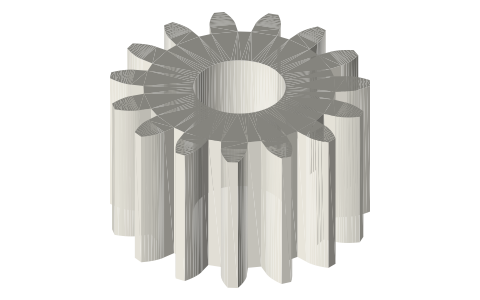
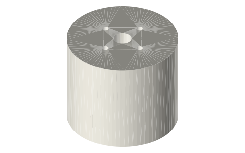
- The crank gear (42 teeth, tip Ø44) sits on the −X crankshaft beside the crank, in place of one flywheel disc and just as heavy; the 15-tooth pinion turns with the motor's rotor. Centre distance 28.5 mm, ratio 2.8 : 1.
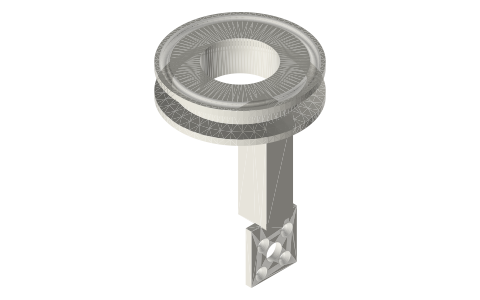
- The pinion rides on an adaptor: a Ø18 × 2 flange bolted to the rotor top with four M2 × 4 (their heads on the flange's outer face) and a Ø6 stub through the pinion, which an M3 grub holds. The rotor's holes sit at r 6, inside the pinion's teeth, so the pinion cannot be bolted on directly.
- Why 2.8 and not more: the motor's Ø27.5 can lies over the crank, so its axis has to be at least 13 + 13.75 mm above the crankshaft (the crank's con-rod eyes sweep R 13), and the crank gear has to turn inside the Ø47.5 bore. 42 : 15 at module 1 puts the can 1.75 mm clear of the crank and the gear tip 1.75 mm inside the bore.
- Both gears are drawn at exact size with no backlash; their teeth are a mating feature (see Mating features).
Step-up gears for a generator inside a 2 in tri-clamp cross: 42 … size chart
| part | teeth | pitch dia (mm) | tip dia (mm) | width (mm) | bore (mm) |
|---|---|---|---|---|---|
| crank gear | 42 | 42.0 | 44.0 | 12.0 | 3.0 |
| pinion | 15 | 15.0 | 17.0 | 10.0 | 6.0 |
| adaptor | 18.0 | 14.0 |
Mating features
Drawn at the exact size. Open press, slide, run and socket features by your process's clearance (tolerances by process); leave designed gaps and clamp fits as drawn.
| feature | exact | mates with | fit | files |
|---|---|---|---|---|
| teeth | module 1, 20°, 42 T and 15 T at 28.5 centre distance, no backlash | each other | designed | all |
| crank-gear bore | Ø3 | Ø3 crankshaft (M3 grub, radial from the rim) | slide | crank-gear-* |
| pinion bore | Ø6 | adaptor stub Ø6 (M3 grub) | slide | pinion-m1-* |
| adaptor stub | Ø6 | pinion bore | slide | pinion-adaptor-* |
| adaptor flange holes | 4 × Ø2.4 on the 12 / 12 pattern | shcs-m2x4 into the motor rotor top | designed | pinion-adaptor-* |
| grub holes | Ø2.5 (M3 tapped) | set-m3x10 (gear), set-m3x3 (pinion) | designed | crank-gear-* |
| grub hole | Ø2.5 (M3 tapped) | set-m3x3 onto the adaptor stub (ends at r 6, inside the r 6.25 root) | designed | pinion-m1-* |
Where the files are
Other publishers' files are linked, not hosted. "verify" = check the license at the link before commercial use.
| ISO | ISO 53 cylindrical gears, standard basic rack (20°, addendum 1 m, dedendum 1.25 m), as the involute spur gears on this site | standard | dimensions are facts verify |
| GetFPV (product listing) | Tiger GB2208-80 gimbal motor: 27.5 × 23, 4.5 hollow shaft, stator 4-M3 on 19 × 16, rotor 4-M2 on 12 × 12 | web | vendor page; dimensions are facts verify |
| Long Earth Society | Engine builds | web, video | LES site |
Free files
★ Free files 3 parts. Xem Studio design: free to use, print and sell things from; not to be republished as files. Xem Studio Design License. index.json
Use this part in your AI. Your AI gets the exact sizes and files straight from Xem and can design a mount, case or adapter around it. Direct downloads here are limited to one file every 10 minutes; through your AI they are unlimited.
Connect Xem to your AI (free, no account, about a minute)
https://xemstudio.com/mcp- Claude: Add to Claude
- ChatGPT (Plus or higher): open Connectors → Advanced → turn on Developer mode → Create → paste the address, no authentication → Create.
- Cursor: install with one click. VS Code: install with one click.
| crank-gear-m1-42t-b3 | crank gear: module 1, 42 teeth, 20° (pitch Ø42, tip Ø44), 12 wide, Ø3 bore, radial M3 tapped hole (Ø2.5) at mid-width | STEP · STL |
| pinion-m1-15t-b6 | pinion: module 1, 15 teeth, 20° (pitch Ø15, tip Ø17), 10 wide, Ø6 bore, radial M3 tapped hole (Ø2.5) | STEP · STL |
| pinion-adaptor-2208 | pinion adaptor: flange Ø18 × 2 with 4 × Ø2.4 on the 12 / 12 rotor pattern, Ø6 stub 12 long | STEP · STL |
https://xemstudio.com/mcp to Claude, ChatGPT, Cursor or any MCP client (free, no account, one minute) and it can look up exact sizes, mating fits and free STEP/STL from every chat.Plain text: sheet.txt · JSON: /api/geometry?object=tri-clamp-generator-step-up-gears
Fits with


Questions
What ratio, and why not more?
2.8 : 1. The motor can has to clear the crank and the gear has to fit the 2 in bore; that sets the centre distance at 28.5 mm.
How much do the gears lose?
A single spur mesh like this loses roughly 1 to 3 % of the power through it; the estimate on the build list uses that range.