 Xem Studiomeasured geometry
Library › Mechanisms › Belt and friction drives ·
Shaft carried on the rims of two pairs of wheels (anti-friction bearing)
What is a friction-wheel bearing? · Hardware · basis: Xem Studio design following Brown No. 250 (1868)
Also called: friction wheel bearing, anti friction rollers, roller bearing (early), cojinete de ruedas antifricción, Friktionsrollenlager
Exact dimensions. True size, with no tolerance added.
- sizes
- 4 in table
Notes
- Resize: multiply every length by one factor k and the motion stays identical: angles, ratios, timing and the formulas below do not change, because a mechanism's motion depends only on the ratios of its lengths. Here, scales with k: wheels, axle spacing; step to the nearest standard size (and redraw the hole or pocket it fits): shaft, shaft height.
- Resize: Speed ratio = driven Ø / driver Ø (or driven / driver teeth), independent of size. Timing belts and chain come in fixed pitches: keep the pitch and change the tooth counts, or step to the next standard pitch.
- Resize: fit clearances stay in mm (a slide fit is the same gap at any size); keep every printed wall and pin at least two nozzle widths; mass grows with k³ but part strength only with k², so at k = 2 parts are about 8× heavier and 4× stronger: check pins and thin links when scaling up.
- Instead of turning in a plain bearing, the shaft lies in the angle between the rims of two wheels whose axles are parallel to it: as the shaft turns, the wheels turn with it, and the sliding friction of a journal becomes rolling friction at the rims plus a small journal friction at the wheels' axles, reduced in the ratio of their diameters.
- Here a Ø10 shaft on Ø40 wheels with axles 44 mm apart: the shaft's centre is 11.87 mm above the axles, touching each rim on a line. Two pairs, 70 mm apart along the shaft.
- Brown's No. 250 (anti-friction bearing: the shaft running on the circumferences of two wheels).
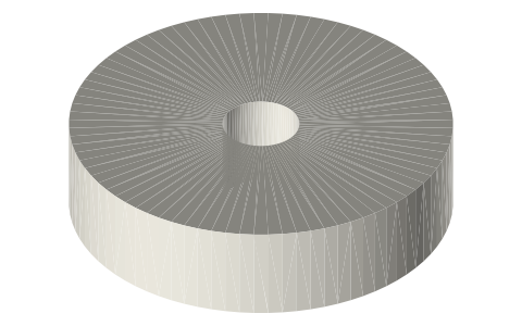
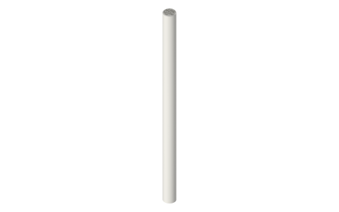
- Parts (each has its own page): anti-friction-wheel-40x10-bore8, linear-shafts-h6.
- Brown's movement No. 250 (1868) shows it; this model is a Xem Studio design following his figure, every part at true size.
Shaft carried on the rims of two pairs of wheels size chart
| parameter | value |
|---|---|
| shaft | Ø10 |
| wheels | 4 × Ø40 × 10 |
| axle spacing | 44 mm |
| shaft height | 11.87 mm |
Where the files are
Other publishers' files are linked, not hosted. "verify" = check the license at the link before commercial use.
| Henry T. Brown (1868, public domain) | Five Hundred and Seven Mechanical Movements — scan on archive.org | web | Publisher's page; dimensions are facts |
| 507movements.com | Brown's movement No. 250: figure, his text and an animation | web | Publisher's page; dimensions are facts |
Free files
★ Free files 1 parts. Xem Studio design: free to use, print and sell things from; not to be republished as files. Xem Studio Design License. index.json
Use this part in your AI. Your AI gets the exact sizes and files straight from Xem and can design a mount, case or adapter around it. Direct downloads here are limited to one file every 10 minutes; through your AI they are unlimited.
Connect Xem to your AI (free, no account, about a minute)
https://xemstudio.com/mcp- Claude: Add to Claude
- ChatGPT (Plus or higher): open Connectors → Advanced → turn on Developer mode → Create → paste the address, no authentication → Create.
- Cursor: install with one click. VS Code: install with one click.
| anti-friction-wheel-bearing-mechanism-assembly | Assembled mechanism, all parts placed at one pose (STEP keeps each part separate) | STEP · STL |
https://xemstudio.com/mcp to Claude, ChatGPT, Cursor or any MCP client (free, no account, one minute) and it can look up exact sizes, mating fits and free STEP/STL from every chat.Plain text: sheet.txt · JSON: /api/geometry?object=anti-friction-wheel-bearing-mechanism

Fits with
Questions
What is a friction-wheel bearing?
Instead of turning in a plain bearing, the shaft lies in the angle between the rims of two wheels whose axles are parallel to it: as the shaft turns, the wheels turn with it, and the sliding friction of a journal becomes rolling friction at the rims plus a small journal friction at the wheels' axles, reduced in the ratio of their diameters.