 Xem Studiomeasured geometry
Library › 3D printing › Calibration & test prints ·
Hall sensor mount for TO-92S (A3144 / SS49E)
How do I mount a hall sensor to measure RPM? · Hardware · basis: Block sized to the A3144 UA / SS49E TO-92S body (4.09 × 1.52 mm), M3 foot hole at ISO 273 clearance (Ø3.4)
Also called: hall sensor mount 3d print, a3144 mount, ss49e holder, hall sensor rpm mount, to92 sensor holder
Used in Long Earth Society builds. Running temperature and RPM measurements
Exact dimensions. Every file is drawn at true size with no tolerance added. The holes and pins that meet another part are listed below under Mating features, with the fit each joint needs; open those by your process's clearance before making the part. Mating features
- sizes
- 4 in table
Notes
- The mount is a 14 × 10 × 20 mm block with a 4.09 × 1.52 × 10 mm deep slot in the top face for a TO-92S (UA) hall sensor body, exact.
- The slot sits 1.24 mm behind one 14 mm face, so the sensor's face is that close to the passing magnet side.
- A Ø3.4 hole (M3 clearance) runs through the 10 mm thickness, 5 mm above the base, for the screw that holds it.
- One magnet passing gives one pulse: rpm = pulses per second × 60 / magnets per revolution; on the 12-pole axial-flux rotor that is pulses × 60 / 12.
Hall sensor mount for TO-92S size chart
| feature | size (mm) |
|---|---|
| block | 14 × 10 × 20 |
| sensor slot | 4.09 × 1.52 × 10 deep |
| slot to face | 1.24 |
| foot hole | Ø3.4 (M3) |
Mating features
Drawn at the exact size. Open press, slide, run and socket features by your process's clearance (tolerances by process); leave designed gaps and clamp fits as drawn.
| feature | exact | mates with | fit | files |
|---|---|---|---|---|
| sensor slot | 4.09 × 1.52 | A3144 UA / SS49E TO-92S body | press | hall-sensor-mount-* |
| foot hole | Ø3.4 | M3 screw clearance | designed | hall-sensor-mount-* |
Where the files are
Other publishers' files are linked, not hosted. "verify" = check the license at the link before commercial use.
| Wikipedia | Thermocouple | web | CC BY-SA 4.0 (text) |
| Wikipedia | Hall effect sensor | web | CC BY-SA 4.0 (text) |
| Wikipedia | Dial indicator | web | CC BY-SA 4.0 (text) |
| Analog Devices | DS18B20 datasheet | Manufacturer datasheet | |
| Long Earth Society | Engine and rig builds | web, video | LES site |
Free files
★ Free files 1 parts. Xem Studio design: free to use, print and sell things from; not to be republished as files. Xem Studio Design License. index.json
Use this part in your AI. Your AI gets the exact sizes and files straight from Xem and can design a mount, case or adapter around it. Direct downloads here are limited to one file every 10 minutes; through your AI they are unlimited.
Connect Xem to your AI (free, no account, about a minute)
https://xemstudio.com/mcp- Claude: Add to Claude
- ChatGPT (Plus or higher): open Connectors → Advanced → turn on Developer mode → Create → paste the address, no authentication → Create.
- Cursor: install with one click. VS Code: install with one click.
| hall-sensor-mount-to92 | hall sensor mount (A3144 UA / SS49E TO-92S): 4.09 × 1.52 body slot, Ø3.4 (M3 clearance) foot hole | STEP · STL |
https://xemstudio.com/mcp to Claude, ChatGPT, Cursor or any MCP client (free, no account, one minute) and it can look up exact sizes, mating fits and free STEP/STL from every chat.Plain text: sheet.txt · JSON: /api/geometry?object=hall-sensor-mount

How it fits
Goes in or on
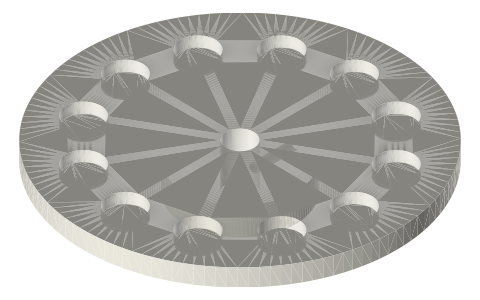 Axial-flux rotor platesfaces a rotor magnet: 12 pulses per revolution
Connects to
 Neodymium disc magnets, common sizessensor face 1–2 mm from a passing magnet
Alternatives
 Optical encoder disc Ø60, 30 slots, Ø5 boreoptical pickup through an IR slot sensor
You might also need

Questions
What size is a TO-92S hall sensor body?
4.09 × 1.52 mm (A3144 UA package, SS49E); the slot is drawn at exactly that.
How do I measure Stirling engine RPM with a hall sensor?
Put the sensor 1–2 mm from a magnet on the flywheel or rotor; rpm = pulses per second × 60 / magnets per revolution.