 Xem Studiomeasured geometry
Library › Hardware › Bearings, rails & motion ·
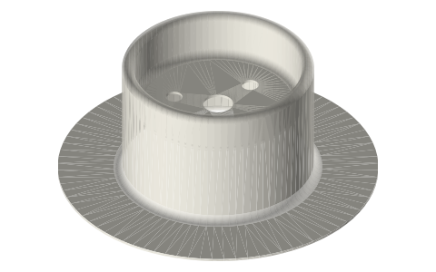
Top-hat rolling diaphragm, 1.50 in bore, flat flange: the one that clamps in a 2 in tri-clamp joint
What size rolling diaphragm fits a 2 inch tri-clamp? · Standard part · basis: Published standard sizes and design rules of top-hat rolling diaphragms (Marsh Bellofram design manual 2022); installed shape drawn by Xem Studio from those numbers
Also called: rolling diaphragm tri clamp, rolling diaphragm stirling engine, top hat diaphragm 1.5 inch, rolling diaphragm size chart, frictionless piston seal, rolling diaphragm dimensions
Long Earth Society build part. I use this diaphragm as the power piston on my rolling-diaphragm tri-clamp engines. It is the answer to my piston-fit problem: nothing slides. Long Earth Society
Exact dimensions. Every file is drawn at true size with no tolerance added. The holes and pins that meet another part are listed below under Mating features, with the fit each joint needs; open those by your process's clearance before making the part. Mating features
- sizes
- 6 in table
Notes
- A rolling diaphragm is a fabric-reinforced top hat. Its flange is clamped, its head is clamped to a piston, and the sidewall rolls in a 180° convolution between the piston and the cylinder bore as the piston moves. Nothing slides, so there is no seal friction and no piston fit: the piston and bore are 2.41 mm apart all round.
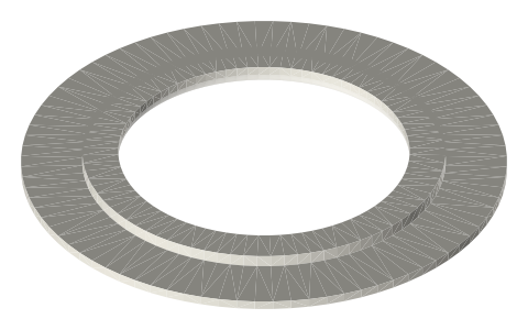
- The flat-flange 1.50 in size has a flange of bore + 1 in = 2.50 in (Ø63.5); the 2 in tri-clamp flange is Ø64.0. So the diaphragm's flange is clamped by a standard 2 in clamp in place of the gasket: between a ferrule's land and the seat ring that sits on the power head's face and in its seat pocket (flange 0.51 + ring 1.19 = the 1.7 web of a Type B gasket).
- Published numbers for this size: bore 1.50 in (Ø38.10), piston 1.31 in (Ø33.27), convolution 0.095 in (2.41), effective area 1.55 in² (1000 mm², the circle on the mean diameter), heights 0.44 / 0.62 / 0.94 / 1.50 in with maximum half strokes 0.06 / 0.24 / 0.56 / 1.12 in; sidewall ≈ 0.017 in, head and flange 0.020 in; flange radius 1/16 in, piston corner radius 1/16 in.
- The file is the 1.50 in high diaphragm as it sits in the power head at mid-stroke: head 15.34 mm below the flange plane, outer wall on the bore, convolution, inner wall on the piston. Over the 20 mm stroke of the power head (head 5.34 to 25.34 mm below the flange, inside the published 28.4 mm) the convolution moves half as far, from 20.0 to 30.0 mm.
- Rules from the same manual that the power head follows: the higher pressure must always be on the head side (a reversal, even brief, can fold the sidewall); the piston is guided so it never tips; the bore mouth and piston edge are radiused; the head is clamped between the piston and a retainer smaller than the piston's flat.
- The published standard range of this flat-flange style runs from 0.37 to 12 in bore; the next sizes either side are 1.37 in (flange 2.37 in) and 1.62 in (flange 2.62 in), which do not match a tri-clamp flange.
- Why not a piston sliding in the tube itself: 2 in sanitary tube is made to its OD (+0.002 / −0.011 in) and wall (0.065 ± 0.008 in), not to its bore, so the bore of one length can be anywhere from 46.8 to 48.0 mm, and it is not round to a sliding-seal standard. A rolling diaphragm runs in its own Ø38.10 bore inside the power head and only needs that bore round within a few tenths.
Top-hat rolling diaphragm, 1.50 in bore, flat flange: the one that… size chart
| bore (in) | piston (in) | convolution (in) | area in2 | height (in) | max half stroke (in) | flange od (in) |
|---|---|---|---|---|---|---|
| 1.37 | 1.19 | 0.09 | 1.28 | 1.37 | 1.0 | 2.37 |
| 1.5 | 1.31 | 0.095 | 1.55 | 0.94 | 0.56 | 2.5 |
| 1.5 | 1.31 | 0.095 | 1.55 | 1.5 | 1.12 | 2.5 |
| 1.62 | 1.44 | 0.09 | 1.83 | 1.62 | 1.25 | 2.62 |
| 1.75 | 1.56 | 0.095 | 2.15 | 1.75 | 1.37 | 2.75 |
| 2.0 | 1.81 | 0.095 | 2.85 | 2.0 | 1.62 | 3.0 |
Mating features
Drawn at the exact size. Open press, slide, run and socket features by your process's clearance (tolerances by process); leave designed gaps and clamp fits as drawn.
| feature | exact | mates with | fit | files |
|---|---|---|---|---|
| flange | Ø63.5 × 0.51 | 2 in ferrule land and the seat ring in the power head's face, closed by a 2 in clamp | clamp | all |
| head | Ø30.1 flat × 0.51 | piston crown, clamped by the head retainer | clamp | all |
| head holes | Ø6 centre, 3 × Ø3.4 on Ø18 | retainer screws (no contact) | designed | all |
| convolution | 2.413 wide (Ø38.10 bore − Ø33.27 piston) / 2 | bore and piston walls | designed | all |
Where the files are
Other publishers' files are linked, not hosted. "verify" = check the license at the link before commercial use.
| Marsh Bellofram | Rolling diaphragm design manual (2022): nomenclature, height formula, standard-size tables, hardware radii | publisher's manual; dimensions cited, nothing copied | |
| Steel & O'Brien | ASTM A270 sanitary tubing: OD and wall tolerances | web | publisher's table; dimensions cited |
| ISO (via iTeh sample) | ISO 2852 clamp liners: face profile and flange / groove diameters | standard excerpt; dimensions are facts | |
| ASME | BPE Bioprocessing Equipment (clamp fitting dimensions, tube OD and wall) | standard | ASME; dimensions are facts verify |
| Long Earth Society | Engine builds | web, video | LES site |
Free files
★ Free files 1 parts. Generated by Xem Studio from the standard; threads are plain cylinders at major diameter. CC BY 4.0. index.json
Use this part in your AI. Your AI gets the exact sizes and files straight from Xem and can design a mount, case or adapter around it. Direct downloads here are limited to one file every 10 minutes; through your AI they are unlimited.
Connect Xem to your AI (free, no account, about a minute)
https://xemstudio.com/mcp- Claude: Add to Claude
- ChatGPT (Plus or higher): open Connectors → Advanced → turn on Developer mode → Create → paste the address, no authentication → Create.
- Cursor: install with one click. VS Code: install with one click.
| rd-diaphragm-1.50-h1.50 | top-hat rolling diaphragm, 1.50 in bore (Ø38.10) × 1.31 in piston (Ø33.27) × 1.50 in high: flat flange Ø63.5 × 0.51, sidewall 0.43, Ø6 centre hole and 3 × Ø3.4 on Ø18 in the head; drawn installed in the 2 in power head at mid-stroke (head 15.34 below the flange, convolution 24.96 below it) | STEP · STL |
https://xemstudio.com/mcp to Claude, ChatGPT, Cursor or any MCP client (free, no account, one minute) and it can look up exact sizes, mating fits and free STEP/STL from every chat.Plain text: sheet.txt · JSON: /api/geometry?object=rolling-diaphragm-top-hat
Fits with


Questions
Which rolling diaphragm fits a 2 in tri-clamp?
The flat-flange 1.50 in bore size: its flange is 2.50 in (63.5 mm) across, the 2 in tri-clamp flange is 64.0 mm, so the clamp holds it in place of the gasket.
How far can it stroke?
The 1.50 in high one up to 1.12 in (28.4 mm) on one side of the flange plane; the power head uses 20 mm of it.
Does the piston have to fit the bore?
No. The piston is 2.41 mm smaller than the bore on each side; the diaphragm rolls in that gap. Round and on size within a few tenths is enough.
What is the catch?
The gas must always push on the head side. If the working gas drops below the pressure behind the diaphragm, the sidewall can fold. Keep the engine's lowest pressure at or above the back side (a one-way valve that lets air in does this).