 Xem Studiomeasured geometry
Library › Tri-clamp & pipe › Clamp fittings ·
Tri-clamp clamp, two-bolt: every flange size ½ to 4 in
What are the dimensions of a two-bolt tri-clamp clamp? · Hardware · basis: Groove derived from the ISO 2852 ferrule: 2.85 mm rim, 20° back cone, C3 rim diameter, Type B gasket web 1.7 mm; contact after 0.4 mm of travel, 0.6 mm more before the halves meet
Also called: tri clamp clamp stl, two bolt tri clamp, tri clamp clamp dimensions, 2 inch tri clamp clamp, sanitary clamp
Used in Long Earth Society builds. 3-foot Stirling engine · Custom high-temperature thermoacoustic engine (final design) · Finned tri-clamp heat sink with PTFE thermal break · Self-starting and restart behavior
Exact dimensions. Every file is drawn at true size with no tolerance added. The holes and pins that meet another part are listed below under Mating features, with the fit each joint needs; open those by your process's clearance before making the part. Mating features
- sizes
- 6 in table
Notes
- A two-bolt clamp in two identical halves; each file is one half. The groove is the ferrule's 20° back cone mirrored, so pulling the halves together wedges the two rims toward each other and squeezes the gasket.
- Designed take-up: each half has 1.0 mm to travel; the groove walls touch the rims after 0.4 mm and the last 0.6 mm squeezes the gasket about 0.44 mm before the halves meet, so a closed split means a seated joint.
- Bore over the tube = tube OD + 2 mm (no contact). Two lugs per half with Ø5.5 holes. The +X lug has a hex pocket 8 AF × 3.5 deep on its outer face that holds an ISO 4017 M5 hex head (s 8, k 3.5) so the screw cannot turn; the −X lug is the plain hole. The second half is the same part turned 180°, so at each bolt one lug holds the head and the M5 nut (ISO 4032) runs down on the other half's plain lug.
- One clamp per flange: the ½–¾ in mini flange (Ø25.0), 1–1½ in (Ø50.5), 2, 2½, 3 and 4 in.
Tri-clamp clamp, two-bolt: every flange size ½ to 4 in size chart
| size (in) | tube od (mm) | rim c3 (mm) | clamp od (mm) | clamp width (mm) | groove throat (mm) | contact after (mm) | bolts |
|---|---|---|---|---|---|---|---|
| ½–¾ | 19.1 | 25.0 | 34.0 | 13.3 | 7.4 | 0.4 | 2 × M5 × 30 hex head (ISO 4017) + nuts |
| 1–1½ | 38.1 | 50.5 | 59.5 | 15.7 | 7.4 | 0.4 | 2 × M5 × 30 hex head (ISO 4017) + nuts |
| 2 | 50.8 | 64.0 | 73.0 | 16.0 | 7.4 | 0.4 | 2 × M5 × 30 hex head (ISO 4017) + nuts |
| 2½ | 63.5 | 77.5 | 86.5 | 16.3 | 7.4 | 0.4 | 2 × M5 × 30 hex head (ISO 4017) + nuts |
| 3 | 76.2 | 91.0 | 100.0 | 16.5 | 7.4 | 0.4 | 2 × M5 × 30 hex head (ISO 4017) + nuts |
| 4 | 101.6 | 119.0 | 128.0 | 17.5 | 7.4 | 0.4 | 2 × M5 × 30 hex head (ISO 4017) + nuts |
Mating features
Drawn at the exact size. Open press, slide, run and socket features by your process's clearance (tolerances by process); leave designed gaps and clamp fits as drawn.
| feature | exact | mates with | fit | files |
|---|---|---|---|---|
| clamp groove | ISO 2852 rim, 20° | two ferrule rims; walls touch after 0.4 mm, 0.6 mm squeeze | designed | clamp-half-* |
| hex pocket (+X lug only) | 8 AF × 3.5 (ISO 4017 M5 head: s 8, k 3.5) | M5 hex head screw head, held from turning | socket | clamp-half-* |
| nut side (−X lug) | Ø5.5 plain through hole, flat outer face | M5 shank; M5 nut (ISO 4032) on the face | designed | clamp-half-* |
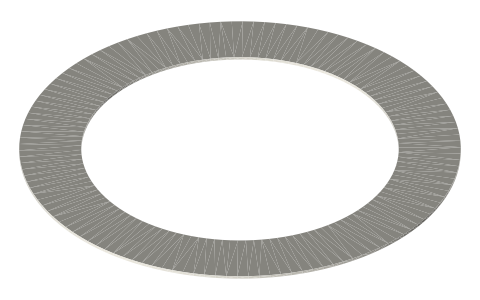
| hot-gasket ring | C3 − 1 × bore × 1.7 (the Type B web) | ferrule faces; the clamp squeezes it in its last 0.6 mm | designed | hot-gasket-* |
| clamp bore over the tube | tube OD + 2 | tube (no contact) | designed | clamp-half-* |
| bolt holes | Ø5.5 | M5 screw clearance (ISO 273) | designed | clamp-half-* |
| split / take-up | 1.0 per half, contact after 0.4 | the other half | designed | clamp-half-* |
| heat-shield bore | flange OD (C3) | ferrule rim it passes over; rests on the clamp | slide | heat-shield-* |
Where the files are
Other publishers' files are linked, not hosted. "verify" = check the license at the link before commercial use.
| ISO | ISO 2852:1993 Stainless steel clamp pipe couplings for the food industry | standard | ISO verify |
| Long Earth Society | Tri-clamp Stirling engine builds | web, video | LES site |
Free files
★ Free files 6 parts. Generated by Xem Studio from the standard; threads are plain cylinders at major diameter. CC BY 4.0. index.json
Use this part in your AI. Your AI gets the exact sizes and files straight from Xem and can design a mount, case or adapter around it. Direct downloads here are limited to one file every 10 minutes; through your AI they are unlimited.
Connect Xem to your AI (free, no account, about a minute)
https://xemstudio.com/mcp- Claude: Add to Claude
- ChatGPT (Plus or higher): open Connectors → Advanced → turn on Developer mode → Create → paste the address, no authentication → Create.
- Cursor: install with one click. VS Code: install with one click.
| clamp-half-0.75in | ½–¾ in two-bolt clamp half (two per clamp): 20° groove for the ISO 2852 rims, contact after 0.4 mm, 0.6 mm squeeze before the halves meet, 2 × M5 × 30 hex head screws (ISO 4017) through Ø5.5 holes: the +X lug's 8 AF × 3.5 pocket holds a screw head, the −X lug is a plain hole with the nut on its outer face; 13.3 mm wide | STEP · STL |
| clamp-half-1.5in | 1–1½ in two-bolt clamp half (two per clamp): 20° groove for the ISO 2852 rims, contact after 0.4 mm, 0.6 mm squeeze before the halves meet, 2 × M5 × 30 hex head screws (ISO 4017) through Ø5.5 holes: the +X lug's 8 AF × 3.5 pocket holds a screw head, the −X lug is a plain hole with the nut on its outer face; 15.7 mm wide | STEP · STL |
| clamp-half-2in | 2 in two-bolt clamp half (two per clamp): 20° groove for the ISO 2852 rims, contact after 0.4 mm, 0.6 mm squeeze before the halves meet, 2 × M5 × 30 hex head screws (ISO 4017) through Ø5.5 holes: the +X lug's 8 AF × 3.5 pocket holds a screw head, the −X lug is a plain hole with the nut on its outer face; 16.0 mm wide | STEP · STL |
| clamp-half-2.5in | 2.5 in two-bolt clamp half (two per clamp): 20° groove for the ISO 2852 rims, contact after 0.4 mm, 0.6 mm squeeze before the halves meet, 2 × M5 × 30 hex head screws (ISO 4017) through Ø5.5 holes: the +X lug's 8 AF × 3.5 pocket holds a screw head, the −X lug is a plain hole with the nut on its outer face; 16.3 mm wide | STEP · STL |
| clamp-half-3in | 3 in two-bolt clamp half (two per clamp): 20° groove for the ISO 2852 rims, contact after 0.4 mm, 0.6 mm squeeze before the halves meet, 2 × M5 × 30 hex head screws (ISO 4017) through Ø5.5 holes: the +X lug's 8 AF × 3.5 pocket holds a screw head, the −X lug is a plain hole with the nut on its outer face; 16.5 mm wide | STEP · STL |
| clamp-half-4in | 4 in two-bolt clamp half (two per clamp): 20° groove for the ISO 2852 rims, contact after 0.4 mm, 0.6 mm squeeze before the halves meet, 2 × M5 × 30 hex head screws (ISO 4017) through Ø5.5 holes: the +X lug's 8 AF × 3.5 pocket holds a screw head, the −X lug is a plain hole with the nut on its outer face; 17.5 mm wide | STEP · STL |
https://xemstudio.com/mcp to Claude, ChatGPT, Cursor or any MCP client (free, no account, one minute) and it can look up exact sizes, mating fits and free STEP/STL from every chat.Plain text: sheet.txt · JSON: /api/geometry?object=tri-clamp-clamps

How it fits
Goes in or on
 Tri-clamp sanitary ferrule, 1/2 to 4 inchgroove fits the ISO 2852 rim and back cone
 Tri-clamp spool, 1.5 and 2 inchany spool joint
 Sanitary clamp weld ferrules, short and mediumany BPE ferrule of the same flange
Alternatives
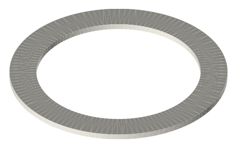 Tri-clamp flat gasketflat gasket at a hot joint
Also needed
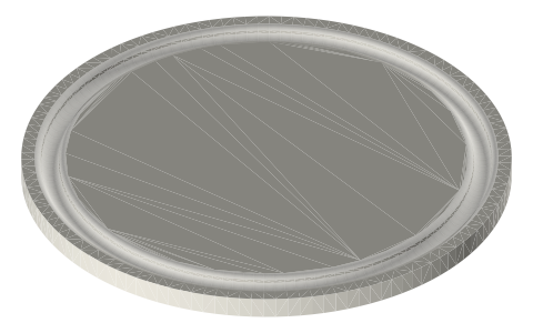 Tri-clamp end cap, 6 mm flatType B gasket for cold joints
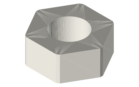 Hex nuts, M2–M8M5 nuts in the traps
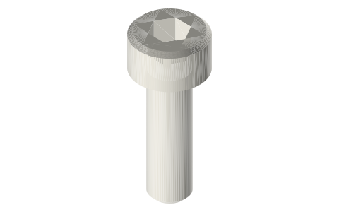 Socket head cap screws, M2–M8M5 × 30
 Wire mesh discs Ø44 / Ø32 × 0.5 mm, mesh #40 to #200mica / ceramic for the hot side
 Tri-clamp gasket, ISO 2852 Type BType B gasket between the faces
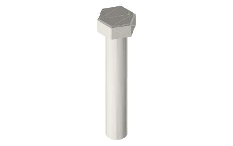 Hex head screws, M3–M8M5 × 30, head in the 8 AF pocket
You might also need

Questions
How does a two-bolt tri-clamp clamp seal?
Its 20° groove wedges the two ferrule rims together: walls touch after 0.4 mm of travel per half, and the last 0.6 mm squeezes the gasket about 0.44 mm.
How tight should the clamp be?
Until the gap between the two halves is closed on both sides; the gasket is then at its designed squeeze.
What bolts does the clamp take?
Two M5 × 30 hex head screws (ISO 4017) through Ø5.5 holes: each head sits in the 8 AF × 3.5 pocket on one half's lug so it cannot turn, and the M5 nut goes on the other half's plain lug.