 Xem Studiomeasured geometry
Library › 3D printing › Calibration & test prints ·
Printed pin gauges 2.8–3.2 and 4.8–5.2 mm
How much over size do printed pins come out? · Hardware · basis: Pins stepped around Ø3 and Ø5 in 0.1 mm steps, tested in the bore of a 623 (Ø3) or 625 (Ø5) bearing
Also called: pin tolerance test print, printed pin calibration, 3d print shaft size test, 623 bearing fit test, spigot tolerance
Long Earth Society build part. Print these first to measure your allowances; every LES part is drawn at exact size. Long Earth Society
Exact dimensions. Every file is drawn at true size with no tolerance added. The holes and pins that meet another part are listed below under Mating features, with the fit each joint needs; open those by your process's clearance before making the part. Mating features
- sizes
- 2 in table
Notes
- Every file on this site is drawn at exact size with no printing allowance; this gauge steps through sizes around the nominal so you can measure the allowance your process needs for one fit class, then apply it only to the features each object lists under Mating features.
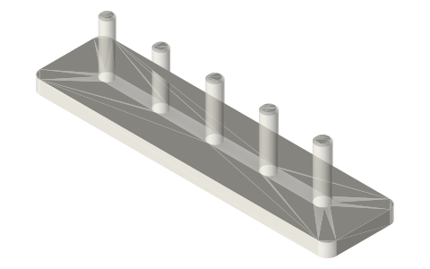
- Each gauge is a 66 × 16 × 3 mm base with five pins 12 mm tall, 0.3 mm chamfered tips: Ø2.8, 2.9, 3.0, 3.1, 3.2 or Ø4.8, 4.9, 5.0, 5.1, 5.2.
- Try each pin in the bore of a 623 (Ø3) or 625 (Ø5) bearing: the pin that enters finger-tight, minus 3.0 or 5.0, is the allowance for printed pins and spigots (usually negative).
Printed pin gauges 2.8–3.2 and 4.8–5.2 mm size chart
| gauge | pins (mm) | test (in) |
|---|---|---|
| pin-gauge-2-8-to-3-2 | 2.8 / 2.9 / 3.0 / 3.1 / 3.2 | 623 bore Ø3 |
| pin-gauge-4-8-to-5-2 | 4.8 / 4.9 / 5.0 / 5.1 / 5.2 | 625 bore Ø5 |
Mating features
Drawn at the exact size. Open press, slide, run and socket features by your process's clearance (tolerances by process); leave designed gaps and clamp fits as drawn.
| feature | exact | mates with | fit | files |
|---|---|---|---|---|
| gauge sizes | stepped around nominal | the true pin, nut, bearing or extrusion slot being tested | designed | all |
Where the files are
Other publishers' files are linked, not hosted. "verify" = check the license at the link before commercial use.
| Wikipedia | Engineering tolerance | web | CC BY-SA 4.0 (text) |
| Prusa | Knowledge base: XY size compensation | web | Prusa KB verify |
| Long Earth Society | Engine and rig builds | web, video | LES site |
Free files
★ Free files 2 parts. Xem Studio design: free to use, print and sell things from; not to be republished as files. Xem Studio Design License. index.json
Use this part in your AI. Your AI gets the exact sizes and files straight from Xem and can design a mount, case or adapter around it. Direct downloads here are limited to one file every 10 minutes; through your AI they are unlimited.
Connect Xem to your AI (free, no account, about a minute)
https://xemstudio.com/mcp- Claude: Add to Claude
- ChatGPT (Plus or higher): open Connectors → Advanced → turn on Developer mode → Create → paste the address, no authentication → Create.
- Cursor: install with one click. VS Code: install with one click.
| pin-gauge-2-8-to-3-2 | printed pin gauge 2.8–3.2: which prints to a true Ø3 hole in a bearing? | STEP · STL |
| pin-gauge-4-8-to-5-2 | printed pin gauge 4.8–5.2 (625 bearing bore test) | STEP · STL |
https://xemstudio.com/mcp to Claude, ChatGPT, Cursor or any MCP client (free, no account, one minute) and it can look up exact sizes, mating fits and free STEP/STL from every chat.Plain text: sheet.txt · JSON: /api/geometry?object=pin-gauges
How it fits
Connects to
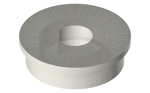 Ball bearings, 683 to 6210 and flanged F6xxpins tried in the Ø3 / Ø5 bore of a 623 / 625
Also needed
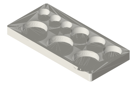
 Hole gauges for Ø3, Ø5 and Ø8the matching inside-diameter test
You might also need
Questions
Why do printed pins come out over size?
Outside features come out fat for the same reasons holes come out small; the pin gauge measures the outside error.
How do I read the pin gauge?
The pin that enters a true Ø3 or Ø5 bearing bore finger-tight, minus the nominal, is your pin allowance.