 Xem Studiomeasured geometry
Library › Hardware › Diaphragms & membranes ·
Can-lid diaphragm set: membrane, clamp rings and centre disc, Ø40 / 50 / 60
What diaphragm set fits the lid of a can? · Standard part · basis: Ring bore = diaphragm working diameter; centre disc at half the bore; 6 × M3 clearance (ISO 273) on the ring
Also called: diaphragm clamp ring stl, stirling diaphragm piston, can engine diaphragm dimensions, diaphragm centre disc
Long Earth Society build part. The printed parts for the LES can engine, sized to the cans, syringes, CDs and bearings in the library. Long Earth Society
Exact dimensions. Every file is drawn at true size with no tolerance added. The holes and pins that meet another part are listed below under Mating features, with the fit each joint needs; open those by your process's clearance before making the part. Mating features
- sizes
- 3 in table
Notes
- The diaphragm power piston of the can engine: a 0.2 mm membrane clamped round its edge between two identical rings, with a stiff centre disc the con-rod screws to.
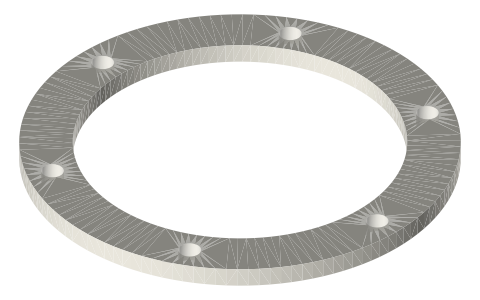
- Rings come in Ø40, Ø50 and Ø60 bores, each 3 thick with an outside of bore + 16 (Ø56 / 66 / 76) and 6 × Ø3.4 holes on a bore + 8 circle (Ø48 / 58 / 68).
- Each ring size has its own centre disc at half the bore: Ø20, Ø25 or Ø30 × 2 with a Ø3.2 hole for the M3 con-rod screw.
- Each membrane is the rings' outside diameter (Ø56 / 66 / 76) × 0.2 with the same six Ø3.4 holes and a Ø3.2 centre hole; its free span is the ring bore. One membrane, two rings and one disc of the same size make one diaphragm.
Can-lid diaphragm set: membrane, clamp rings and centre disc, Ø40 /… size chart
| size | ring bore | ring outside | screw circle | ring thickness | disc | disc hole |
|---|---|---|---|---|---|---|
| 40 | 40 | 56 | 48 | 3 | Ø20 × 2 | 3.2 |
| 50 | 50 | 66 | 58 | 3 | Ø25 × 2 | 3.2 |
| 60 | 60 | 76 | 68 | 3 | Ø30 × 2 | 3.2 |
Mating features
Drawn at the exact size. Open press, slide, run and socket features by your process's clearance (tolerances by process); leave designed gaps and clamp fits as drawn.
| feature | exact | mates with | fit | files |
|---|---|---|---|---|
| clamp-ring screw holes | Ø3.4 | M3 screw clearance | designed | diaphragm-ring-* |
| centre-disc screw hole | Ø3.2 | M3 screw clearance (ISO 273 fine) | designed | diaphragm-disc-* |
Where the files are
Other publishers' files are linked, not hosted. "verify" = check the license at the link before commercial use.
| Wikipedia | Stirling engine | web | CC BY-SA 4.0 (text) |
| Long Earth Society | Can engine build | video, web | LES site |
| Long Earth Society | Engine builds (videos and write-ups) | web, video | LES site |
Free files
★ Free files 9 parts. Xem Studio design: free to use, print and sell things from; not to be republished as files. Xem Studio Design License. index.json
Use this part in your AI. Your AI gets the exact sizes and files straight from Xem and can design a mount, case or adapter around it. Direct downloads here are limited to one file every 10 minutes; through your AI they are unlimited.
Connect Xem to your AI (free, no account, about a minute)
https://xemstudio.com/mcp- Claude: Add to Claude
- ChatGPT (Plus or higher): open Connectors → Advanced → turn on Developer mode → Create → paste the address, no authentication → Create.
- Cursor: install with one click. VS Code: install with one click.
| diaphragm-ring-40 | diaphragm clamp ring Ø40 bore × Ø56, 3 thick, 6 × Ø3.4 (M3 clearance); two per diaphragm, one each side of the membrane | STEP · STL |
| diaphragm-disc-20 | diaphragm centre disc Ø20 × 2, Ø3.2 M3 clearance hole for the con-rod screw | STEP · STL |
| diaphragm-membrane-40 | diaphragm membrane Ø56 × 0.2 with the rings' 6 × Ø3.4 holes and a Ø3.2 centre hole; free span Ø40 between the rings | STEP · STL |
| diaphragm-ring-50 | diaphragm clamp ring Ø50 bore × Ø66, 3 thick, 6 × Ø3.4 (M3 clearance); two per diaphragm, one each side of the membrane | STEP · STL |
| diaphragm-disc-25 | diaphragm centre disc Ø25 × 2, Ø3.2 M3 clearance hole for the con-rod screw | STEP · STL |
| diaphragm-membrane-50 | diaphragm membrane Ø66 × 0.2 with the rings' 6 × Ø3.4 holes and a Ø3.2 centre hole; free span Ø50 between the rings | STEP · STL |
| diaphragm-ring-60 | diaphragm clamp ring Ø60 bore × Ø76, 3 thick, 6 × Ø3.4 (M3 clearance); two per diaphragm, one each side of the membrane | STEP · STL |
| diaphragm-disc-30 | diaphragm centre disc Ø30 × 2, Ø3.2 M3 clearance hole for the con-rod screw | STEP · STL |
| diaphragm-membrane-60 | diaphragm membrane Ø76 × 0.2 with the rings' 6 × Ø3.4 holes and a Ø3.2 centre hole; free span Ø60 between the rings | STEP · STL |
https://xemstudio.com/mcp to Claude, ChatGPT, Cursor or any MCP client (free, no account, one minute) and it can look up exact sizes, mating fits and free STEP/STL from every chat.Plain text: sheet.txt · JSON: /api/geometry?object=can-lid-diaphragm-set
How it fits
Connects to
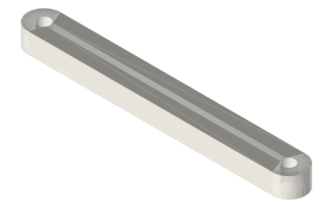 Con-rods with Ø3 pin ends, 45 and 60 mm, 8 × 5con-rod screwed to the centre disc's Ø3.2 hole
Alternatives
 Syringe cradles for 10, 20 and 60 mL barrelsa syringe as the power piston instead
Also needed
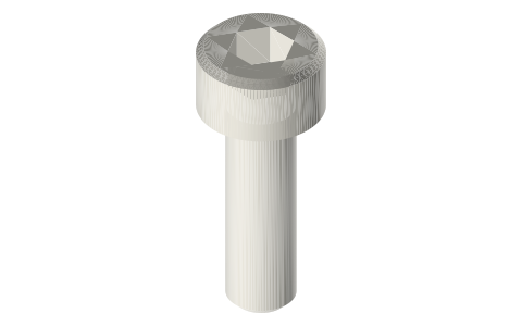 Socket head cap screws, M2–M86 × M3 through the rings, 1 × M3 in the disc
You might also need

Questions
Which centre disc goes with which ring?
Half the ring bore: Ø20 disc with the Ø40 rings, Ø25 with Ø50, Ø30 with Ø60.
How are the diaphragm rings fastened?
Six M3 screws through Ø3.4 holes on a circle 8 mm larger than the bore (Ø58 on the 50 mm ring), through both rings and the membrane.
Which size does the can engine use?
The can-engine build list uses the Ø50 rings with the Ø25 disc.