 Xem Studiomeasured geometry
Library › Hardware › Framing ·
4040 aluminum extrusion, 10 mm slot (40-series)
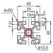
What are the exact dimensions of 4040 aluminum extrusion? · Hardware · basis: Misumi 8 series, 10 mm slot, from Misumi's dimensioned drawing of this profile; every slot, lip, cavity, bore and outline number is the drawing's
Also called: 4040 extrusion step, 4040 extrusion dxf, 4040 extrusion dimensions, 4040 aluminum extrusion cad, 40x40 extrusion profile, 4040 t slot profile, 40x40 extrusion, 4040 extrusion, 80/20 style 4040, 4040 profile 10 mm slot, 4040 b-type extrusion, perfil de aluminio 4040, perfil de alumínio 4040
Exact dimensions. Every file is drawn at true size with no tolerance added. The holes and pins that meet another part are listed below under Mating features, with the fit each joint needs; open those by your process's clearance before making the part. Mating features
- width
- 40.0 mm
- height
- 40.0 mm
Notes
- 4040 aluminum extrusion, 10 mm slot (40-series): 40 × 40 mm, 4 slots on a 40 mm pitch (Misumi 8 series, 10 mm slot). Source: Misumi's dimensioned drawing of this profile. Files: STEP and STL at 100, 150, 200, 250, 300, 350, 400, 450, 500, 600, 750, 1000, 1200, 1500 mm with square ends, and a DXF of the exact cross-section (mm), the master to extrude to any length. The section is centred on the origin and extruded along +Z from z = 0.
- Slot: opening 10 mm, lip 5.5 mm thick at the opening, cavity 20 mm wide under the lips, 12.5 mm from the face to the cavity floor. Centre bore Ø10.5 mm per cell (the largest thread whose tap drill fits inside: M12, 10.2 mm).
- Cavity side walls: the drawing gives the cavity width (20 mm) and depths but not the web thickness, so the side walls run at 45° from the corner under each lip straight to the floor: the smallest cavity those numbers allow. The bar has at least the real metal there, and a part that fits this cavity fits the real one.
- Outer corners R3 (stated). Also drawn: 6 × 6 mm closed corner pockets 2 mm in from both faces (stated; their corner radii are not given, drawn square).
- Wrapping it: to make a part that fits around the bar, subtract the 1000 mm file (or extrude the DXF) from your solid; the outline is the drawing's 40 × 40 mm with no allowance, so open the pocket by your process's socket fit (see Mating features).
- Attachments: the 40-series (10 mm slot) T-nuts, end caps, feet, brackets, gussets, plates and slot covers are cut from these same numbers; the fit check (tools/asm_extrusion_fit.py) placed each one on this profile with zero overlap.
4040 aluminum extrusion, 10 mm slot size chart
| feature | size | from |
|---|---|---|
| outline | 40 × 40 mm, R3 corners | drawing |
| slot pitch | 40 mm | drawing |
| slot opening | 10 mm | drawing |
| lip thickness at the opening | 5.5 mm | drawing |
| cavity width under the lips | 20 mm | drawing |
| face to cavity floor | 12.5 mm | drawing |
| cavity depth under the lip (at the cavity wall) | 7 mm | drawing |
| core between opposite floors | 15 mm | pitch − 2 × face-to-floor |
| diagonal web | not given (45° walls from the cavity corner) | assumed minimum cavity |
| centre bore | Ø10.5 mm × 1 | drawing |
| corner pockets | 6 × 6, 2 in from the faces | drawing |
| cross-section area | 640 mm² | maker's page |
| mass | 1.73 kg/m | maker's page |
| Ix / Iy | 10.4 × 10⁴ / 10.4 × 10⁴ mm⁴ | maker's page |
| area of this model's section | 777.7 mm² | computed from the DXF |
Mating features
Drawn at the exact size. Open press, slide, run and socket features by your process's clearance (tolerances by process); leave designed gaps and clamp fits as drawn.
| feature | exact | mates with | fit | files |
|---|---|---|---|---|
| slot opening | 10 | T-nut tongue, slot-cover stem (40-series (10 mm slot)) | slide | all |
| slot cavity | 20 wide under the lips, face to floor 12.5, lip 5.5 | T-nut body (slide-in, drop-in) | slide | all |
| centre bore | Ø10.5 | M12 thread (tap drill 10.2); end-cap pin | designed | all |
| outline | 40 × 40, R3 | end-cap outline, foot socket, a pocket that wraps the bar | socket | all |
Where the files are
Other publishers' files are linked, not hosted. "verify" = check the license at the link before commercial use.
| Misumi | 40x40 Aluminum Extrusion - 8 Series, Base 40: product page with the cross-section drawing and section properties | web | Misumi site terms verify |
| Misumi | 4040 dimensioned cross-section drawing | image | Misumi site terms verify |
Free files
★ Free files 14 parts. Generated by Xem Studio from the standard; threads are plain cylinders at major diameter. CC BY 4.0. index.json
Use this part in your AI. Your AI gets the exact sizes and files straight from Xem and can design a mount, case or adapter around it. Direct downloads here are limited to one file every 10 minutes; through your AI they are unlimited.
Connect Xem to your AI (free, no account, about a minute)
https://xemstudio.com/mcp- Claude: Add to Claude
- ChatGPT (Plus or higher): open Connectors → Advanced → turn on Developer mode → Create → paste the address, no authentication → Create.
- Cursor: install with one click. VS Code: install with one click.
| 4040-100 | 4040 aluminum extrusion, 10 mm slot (40-series): 40 × 40 mm section, 100 mm long, square ends; DXF = the exact cross-section in mm | STEP · STL · DXF |
| 4040-150 | 4040 aluminum extrusion, 10 mm slot (40-series): 40 × 40 mm section, 150 mm long, square ends; DXF = the exact cross-section in mm | STEP · STL · DXF |
| 4040-200 | 4040 aluminum extrusion, 10 mm slot (40-series): 40 × 40 mm section, 200 mm long, square ends; DXF = the exact cross-section in mm | STEP · STL · DXF |
| 4040-250 | 4040 aluminum extrusion, 10 mm slot (40-series): 40 × 40 mm section, 250 mm long, square ends; DXF = the exact cross-section in mm | STEP · STL · DXF |
| 4040-300 | 4040 aluminum extrusion, 10 mm slot (40-series): 40 × 40 mm section, 300 mm long, square ends; DXF = the exact cross-section in mm | STEP · STL · DXF |
| 4040-350 | 4040 aluminum extrusion, 10 mm slot (40-series): 40 × 40 mm section, 350 mm long, square ends; DXF = the exact cross-section in mm | STEP · STL · DXF |
| 4040-400 | 4040 aluminum extrusion, 10 mm slot (40-series): 40 × 40 mm section, 400 mm long, square ends; DXF = the exact cross-section in mm | STEP · STL · DXF |
| 4040-450 | 4040 aluminum extrusion, 10 mm slot (40-series): 40 × 40 mm section, 450 mm long, square ends; DXF = the exact cross-section in mm | STEP · STL · DXF |
| 4040-500 | 4040 aluminum extrusion, 10 mm slot (40-series): 40 × 40 mm section, 500 mm long, square ends; DXF = the exact cross-section in mm | STEP · STL · DXF |
| 4040-600 | 4040 aluminum extrusion, 10 mm slot (40-series): 40 × 40 mm section, 600 mm long, square ends; DXF = the exact cross-section in mm | STEP · STL · DXF |
| 4040-750 | 4040 aluminum extrusion, 10 mm slot (40-series): 40 × 40 mm section, 750 mm long, square ends; DXF = the exact cross-section in mm | STEP · STL · DXF |
| 4040-1000 | 4040 aluminum extrusion, 10 mm slot (40-series): 40 × 40 mm section, 1000 mm long, square ends; DXF = the exact cross-section in mm | STEP · STL · DXF |
| 4040-1200 | 4040 aluminum extrusion, 10 mm slot (40-series): 40 × 40 mm section, 1200 mm long, square ends; DXF = the exact cross-section in mm | STEP · STL · DXF |
| 4040-1500 | 4040 aluminum extrusion, 10 mm slot (40-series): 40 × 40 mm section, 1500 mm long, square ends; DXF = the exact cross-section in mm | STEP · STL · DXF |
https://xemstudio.com/mcp to Claude, ChatGPT, Cursor or any MCP client (free, no account, one minute) and it can look up exact sizes, mating fits and free STEP/STL from every chat.Plain text: sheet.txt · JSON: /api/geometry?object=4040-aluminum-extrusion
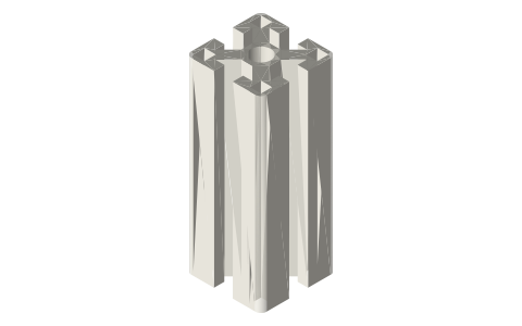
How it fits
Parts that fit it
 Slide-in T-nuts for 20, 30, 40, 45 mm and 1 in,…tongue in the opening, body in the cavity (slide)
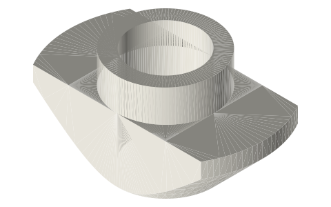 Drop-in T-nuts for 20, 30, 40, 45 mm and 1 in,…drops through the opening, turns 90° in the cavity
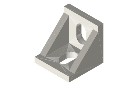 L corner brackets for 20, 30, 40, 45 mm and 1 in,…legs flat on two profile faces at 90°
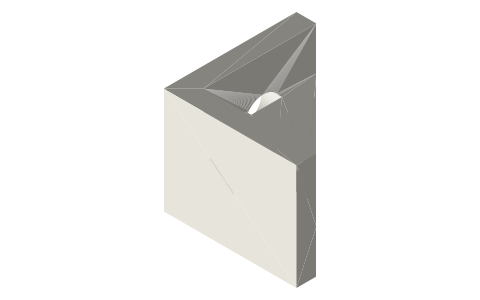 Inside corner gussets for 20, 30, 40, 45 mm and 1…legs on two profile faces in the inside corner
 Snap-in slot covers for 20, 30, 40, 45 mm and 1…stem in the slot opening, barb behind the lips
 Extrusion end feet for 20, 30, 40, 45 mm and 1…profile end in the socket (socket fit)
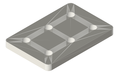 Joining plates, 2 × 3 holes, for 20, 30, 40, 45…holes over the slot centrelines on the profile pitch
 End caps for every T-slot profile hereend-cap-40-1x1: pins in the centre bores (press)
Alternatives
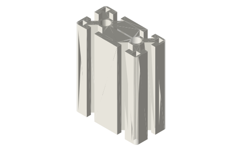 4080 aluminum extrusion, 10 mm slotsame 40-series (10 mm slot) slot, 40 × 80 mm
 8080 aluminum extrusion, 10 mm slotsame 40-series (10 mm slot) slot, 80 × 80 mm
Also needed
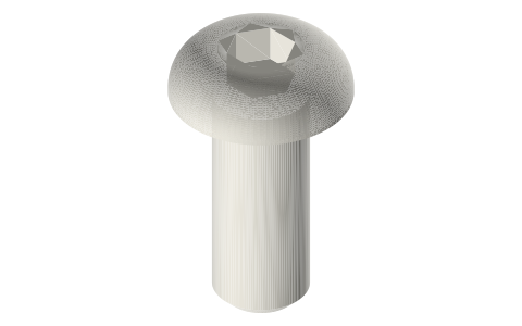 Button head socket screws, M2–M8M8 screws through brackets into the T-nuts
You might also need
Questions
What is the slot size of 4040 extrusion?
Opening 10 mm, lip 5.5 mm, cavity 20 mm wide under the lips and 12.5 mm deep from the face to the floor, per Misumi 8 series, 10 mm slot's drawing.
What T-nuts fit 4040 extrusion?
The 40-series (10 mm slot) nuts: slide-in (tnut-slide-40-m6, tnut-slide-40-m8) and drop-in versions, threaded M6, M8 as tap-drill holes, cut to this slot's exact space.
Can I subtract this file to make a part that fits the extrusion exactly?
Yes: the outline is exactly 40 × 40 mm with R3 corners; extrude the DXF or subtract the 1000 mm STEP, then open the pocket by your fit.
How heavy is 4040 extrusion?
1.73 kg/m, 640 mm² section, as Misumi states. This model's section is larger because closed hollows / cavity details the drawing leaves undimensioned are drawn filled; use the stated weight, not the model's volume.
What in this model is not taken straight from the drawing?
Cavity side walls: the drawing gives the cavity width (20 mm) and depths but not the web thickness, so the side walls run at 45° from the corner under each lip straight to the floor: the smallest cavity those numbers allow. The bar has at least the real metal there, and a part that fits this cavity fits the real one.