 Xem Studiomeasured geometry
Library › Hardware › Gears, cranks & flywheels ·
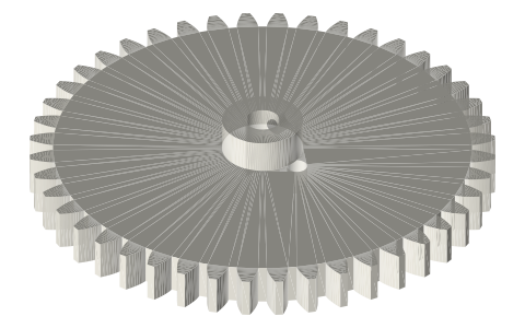
Rhombic drive gear, module 1.5, 44 T, 7 mm throw
What gear pair makes a rhombic drive? · Hardware · basis: Involute spur gear module 1.5, 44 teeth, 20° pressure angle (pitch Ø66); two of them on 66 mm centres; crank pin at e = 7, a quarter tooth pitch off a tooth centre; rhombic kinematics in tools/rhombic_geom.py
Also called: rhombic drive gear, rhombic drive crank gear stl, 30 tooth module 1 crank gear, rhombic drive dimensions
Long Earth Society build part. The balanced beta drive for the 2 in tri-clamp engine; the rhombic frame head in the linkage fittings carries it on the spool. Long Earth Society
Exact dimensions. Every file is drawn at true size with no tolerance added. The holes and pins that meet another part are listed below under Mating features, with the fit each joint needs; open those by your process's clearance before making the part. Mating features
- sizes
- 9 in table
Notes
- The two counter-rotating gears of the rhombic drive are this one part used twice: module 1.5, 44 teeth, pitch Ø66, tip Ø69, 6 face, Ø12 × 5 hub with an M3 grub (Ø2.5 tapped), Ø5 bore (fit: slide).
- Crank-pin hole Ø3 (fit: press) at 7 mm from the axis and 2.045° (a quarter tooth pitch) from a tooth centre. With the two gears mirror images of each other (both pins at the same height), a tooth of one then sits in a gap of the other on the 66 mm centre line: the pin layout and the mesh agree.
- With the 30 mm links and yoke pivots at ±12.7 the displacer leads the piston by 90.0° and both strokes are 20.12 mm.
Rhombic drive gear, module 1.5, 44 T, 7 mm throw size chart
| parameter | value |
|---|---|
| module | 1.5 |
| teeth | 44 |
| pitch Ø | 66.0 |
| tip Ø | 69.0 |
| face width | 6.0 |
| hub | Ø12 × 5 |
| bore | Ø5 |
| crank pin | Ø3 at 7, 2.045° off a tooth |
| gear centres | 66.0 |
Mating features
Drawn at the exact size. Open press, slide, run and socket features by your process's clearance (tolerances by process); leave designed gaps and clamp fits as drawn.
| feature | exact | mates with | fit | files |
|---|---|---|---|---|
| gear bore | Ø5 | Ø5 gear shaft | slide | crank-gear-* |
| gear crank-pin hole | Ø3 | Ø3 crank pin | press | crank-gear-* |
| gear hub grub hole | Ø2.5 | M3 tap drill | designed | crank-gear-* |
| gear teeth | module 1.5, 44 T, 20°, on 66 mm centres | the other crank gear (no backlash drawn) | run | crank-gear-* |
Where the files are
Other publishers' files are linked, not hosted. "verify" = check the license at the link before commercial use.
| Wikipedia | Rhombic drive | web | CC BY-SA 4.0 (text) |
| Wikipedia | Stirling engine | web | CC BY-SA 4.0 (text) |
| Philips Research / Meijer | The Philips Stirling engine (rhombic drive papers, 1958–1965) | web | reference verify |
| Long Earth Society | Engine builds | web, video | LES site |
Free files
★ Free files 1 parts. Xem Studio design: free to use, print and sell things from; not to be republished as files. Xem Studio Design License. index.json
Use this part in your AI. Your AI gets the exact sizes and files straight from Xem and can design a mount, case or adapter around it. Direct downloads here are limited to one file every 10 minutes; through your AI they are unlimited.
Connect Xem to your AI (free, no account, about a minute)
https://xemstudio.com/mcp- Claude: Add to Claude
- ChatGPT (Plus or higher): open Connectors → Advanced → turn on Developer mode → Create → paste the address, no authentication → Create.
- Cursor: install with one click. VS Code: install with one click.
| crank-gear-m1.5-44t-e7 | crank gear module 1.5, 44 teeth (Ø66 pitch, Ø69 tip), 6 face, Ø12 × 5 hub with an M3 grub (Ø2.5 tapped), Ø5 bore, Ø3 crank-pin hole at 7 mm, 2.045° (a quarter tooth pitch) off a tooth centre; two per drive, meshed on 66 mm centres | STEP · STL |
https://xemstudio.com/mcp to Claude, ChatGPT, Cursor or any MCP client (free, no account, one minute) and it can look up exact sizes, mating fits and free STEP/STL from every chat.Plain text: sheet.txt · JSON: /api/geometry?object=rhombic-crank-gear
How it fits
Goes in or on
 2 in tri-clamp cap with two gear-shaft wallsØ5 gear shafts in the head's 625s, 66 mm centres
Connects to
 Rhombic drive crank pin Ø3 × 17Ø3 pin pressed in the gear at 7 mm
 Rhombic drive link, 30 mm centrestwo links ride each crank pin
Alternatives
 Spur gears, involute 20°other involute gears
Also needed
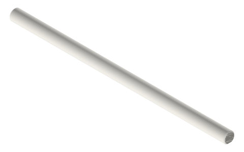 Crankshafts Ø3, Ø5 and Ø8 with full-length D-flatØ5 gear shafts
You might also need

Questions
What gears does a rhombic drive use?
Two identical spur gears turning opposite ways; here module 1.5, 44 T on 66 mm centres, each with a crank pin at 7 mm.
How are the rhombic gears timed?
Mesh them with the two crank pins level and mirror images of each other; the pin hole sits a quarter tooth pitch off a tooth so that position meshes.
What stroke do these gears give?
20.12 mm on both yokes with the 30 mm links (about 2√2 × the 7 mm throw at a 90° phase).